gracezhang@yijiecool.com |
  English
 Español
 عربى
عربى


Condensadores y Evaporadores: How Heat Exchangers Work and How to Specify Them
Content
- 1 The Short Answer: One Loop, Two Opposite Jobs
- 2 What Each Coil Actually Does
- 3 Condenser and Evaporator, Side by Side
- 4 Material Choice: Aluminum Tube, Copper Tube, or a Mix
- 5 Matching the Coil to the Application
- 6 The Numbers Buyers Get Wrong
- 7 Verification Before You Sign
- 8 Where Coils Fail in the Field
- 9 What to Send a Coil Supplier
A buyer compares two quotes for the same duty: a 9 kW direct-expansion evaporator for a rooftop unit. One supplier ships in 21 days, the other in 45. The price gap is 34 percent. Both drawings show the same face area, the same fin spacing, and the same tube diameter. The difference hides in three lines of the specification nobody reads closely — circuit count, tube wall thickness, and the temper of the aluminum alloy.
This is the everyday reality of buying condensers and evaporators. The two components look alike on a drawing, share most of their manufacturing process, and behave completely differently once refrigerant starts moving through them. What follows is what actually separates a coil that holds its capacity for ten years from one that loses it in two, and how to tell the difference before a purchase order is signed.
The Short Answer: One Loop, Two Opposite Jobs
A condenser rejects heat to the environment. An evaporator absorbs heat from the space or the product being cooled. Both are two-phase heat exchangers, both are usually built from the same tube-and-fin technology, and they are almost never interchangeable, because refrigerant enters each one in a different state and leaves it in a different state. Get the heat load right but the pressure drop wrong, and the system still fails — normally at the compressor, not at the coil.
That single sentence explains most of what follows. Sizing, material, circuiting, and testing all exist to keep those two opposite jobs from interfering with each other.
What Each Coil Actually Does
The Evaporator
Liquid refrigerant enters through a distributor or a capillary tube at low pressure. As it travels through the circuits it boils, pulling heat out of the air pushed across the fins. At the outlet the refrigerant should be superheated vapor, usually 5 to 8 K above saturation, so that no liquid droplets reach the compressor. The coil therefore has to satisfy two conditions at once: enough surface area to move the design heat load, and enough circuit length to boil the charge completely at the lowest ambient the unit will ever see.
Two consequences follow. A starved evaporator loses capacity quietly: suction pressure looks acceptable while the room temperature creeps upward. And an oversized evaporator is not a safety margin — it lowers refrigerant velocity, oil returns poorly, and the coil fouls faster because the fin surface runs colder and wetter than it should.
The Condenser
The condenser works through three zones in sequence: desuperheating, condensing, and subcooling. Most of the surface is doing the middle job, which is why condenser performance is driven mainly by air flow and approach temperature rather than by refrigerant velocity. A subcooling value of 3 to 8 K at the outlet is the practical sign that the coil is matched to the charge. Too little subcooling means flash gas at the expansion device; too much means liquid backing up and a rising discharge pressure.
Condenser and Evaporator, Side by Side
| Parameter | Evaporator | Condenser |
|---|---|---|
| Heat flow | Absorbs heat from air or product | Rejects heat to ambient air |
| Refrigerant in | Liquid, low pressure | Superheated vapor, high pressure |
| Refrigerant out | Superheated vapor, 5-8 K superheat | Subcooled liquid, 3-8 K subcooling |
| Operating side | Low side | High side |
| Typical location | Inside the served space or duct | Outdoors or in an exhaust air stream |
| Air side | Cooled, often dehumidified | Warm and dry |
| Fin spacing tendency | Wider, 8-12 FPI, to shed condensate | Tighter, 10-16 FPI, for compactness |
| Dominant failure mode | Fouling, icing, refrigerant starvation | Corrosion, airflow blockage, overcharge |
Material Choice: Aluminum Tube, Copper Tube, or a Mix
Three constructions dominate the market, and each one solves a different problem.
- Copper tube with aluminum fins — the best thermal conductivity, the easiest to braze and repair in the field, and the highest material cost.
- Aluminum tube with aluminum fins — lower material cost, often quoted as 30 percent or more on the tube bundle, no galvanic couple between tube and fin, but it requires controlled-atmosphere brazing and careful handling at the joints.
- Copper tube with copper fins — rare outside marine and heavily corrosive duty, where first cost is secondary to service life.
Thermal conductivity is the argument people reach for first, and it is the weakest one. Copper conducts roughly 400 W/m·K against about 237 for aluminum, but the wall of an aluminum tube is usually thicker and the fin geometry is retuned to compensate. The decision is better made on corrosion environment, joining process, weight, and repair policy. On a coastal installation the alloy and the coating matter more than the base metal; inland, inside a dry cabinet, the difference is largely commercial.
Copper Tube, Aluminum Fin Coils
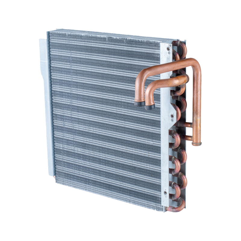
Where a mechanical joint has to survive field repair, a copper-tube coil with aluminum fins remains the pragmatic choice. It tolerates conventional brazing with a torch, accepts standard fittings, and lets a technician replace a failed circuit on site instead of scrapping the whole assembly.
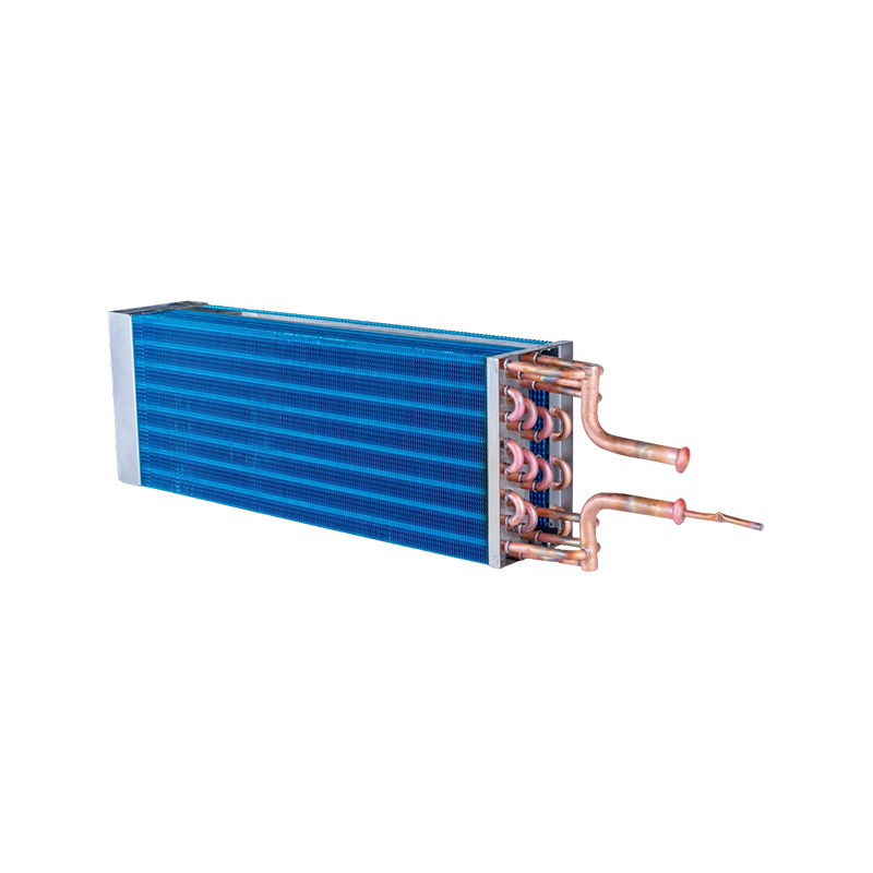 Copper-Tube Aluminum-Fin Evaporator for HVAC Cooling SystemsCompact heat exchanger with copper piping and hydrophilic aluminum fins, suited to HVAC, portable cooling and industrial thermal management where serviceable brazed joints matter.View Product →
Matching the Coil to the Application
Application decides geometry long before thermodynamics does. A coil that works in a dehumidifier will not survive a grain silo, and the same nominal capacity can be built in footprints that differ by a factor of three. Four groups cover most of the volume in the market.
Automotive and Transport
Transport coils live with vibration, stone impact, and tight packaging. A parallel-flow condenser may sit at the front end while a tube-and-fin evaporator works inside the cabin HVAC module. Wall thickness and header design matter more here than nominal capacity, because a pinhole leak on the road becomes a warranty claim rather than a service call.
Household and Light Commercial
Domestic air conditioners, dehumidifiers, water dispensers, ice makers, and air-source heat pumps all use fin-and-tube coils with 7 mm or 9.52 mm tubes. The design priority is usually noise, condensate management, and a footprint that fits an appliance cabinet that was never designed around a heat exchanger.
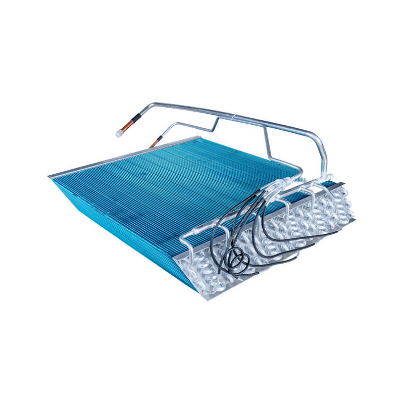
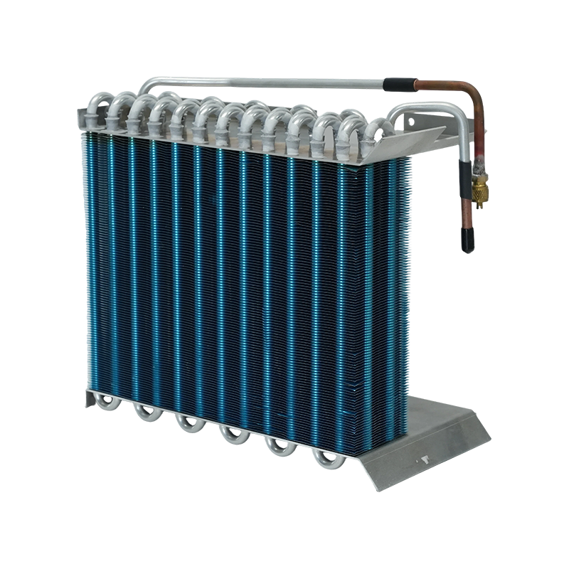 Household Evaporator for Residential Air Conditioning and CoolingResidential AC evaporator with hydrophilic aluminum fins andall-copper piping, designed for compact household HVAC integration and efficient condensate drainage.View Product →
Cold Chain and Food Storage
Freezer and cold-room coils run at low evaporating temperatures, which means larger surface areas, wider fin spacing to manage frost, and a condenser that still has to reject heat on a 40 °C day. Defrost cycles are the real design driver: a coil that drains poorly will ice up within weeks regardless of how well it performs on paper.
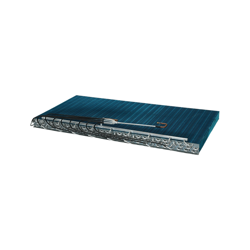
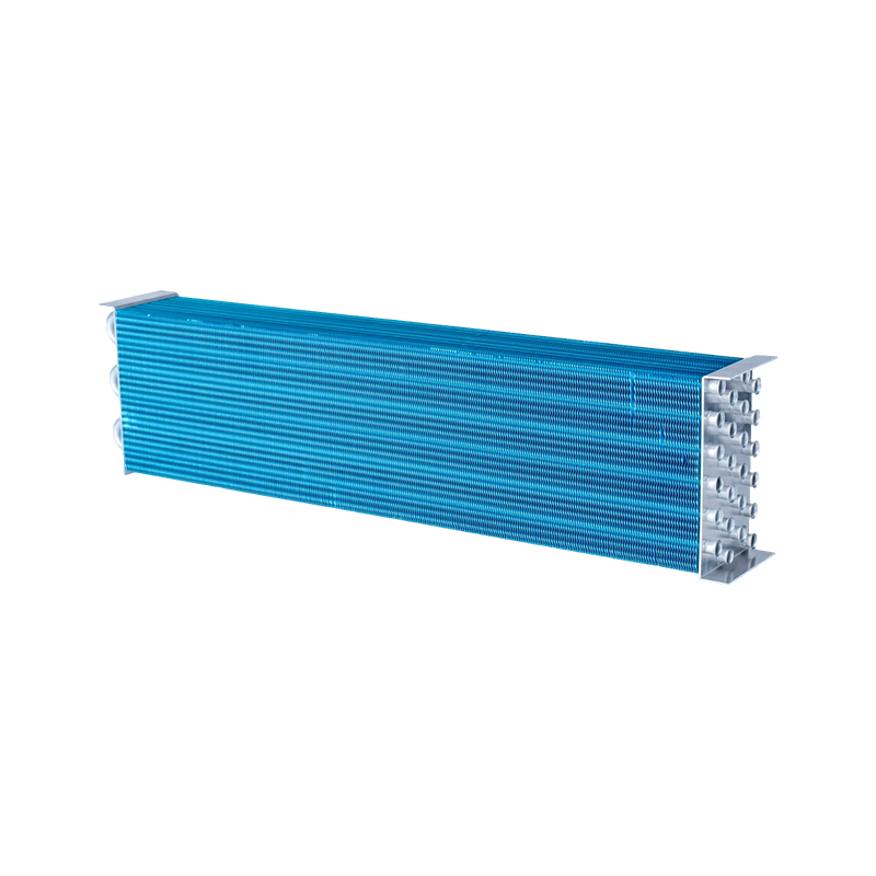
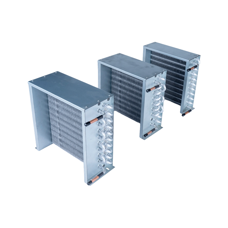 Aluminum Tube Freezer Condenser for Refrigeration Cooling UnitsCompact freezer condenser with corrugated plain foil fins and copper-aluminum welded piping, intended for household and commercial refrigeration systems needing reliable cooling.View Product →
Cabinets, Granaries, and Tight Spaces
Telecom cabinets, grain stores, and machine enclosures need compact coils with high fin density, coated surfaces, and enough static pressure capability to push air through a filter. These units are often running continuously in dusty air, so cleanability belongs in the specification from day one.
The Numbers Buyers Get Wrong
Most disputes over coil performance trace back to one of six items on the specification sheet.
- Face area against actual air flow. Quoted capacity assumes a flow rate that the fan may never deliver once a filter and a duct run are added.
- Fin density. Going from 10 to 14 FPI adds surface area, but it also adds air-side pressure drop and halves the time between cleanings in a dirty environment.
- Tube diameter. Moving from 9.52 mm to 7 mm reduces internal volume and refrigerant charge, but it also changes pressure drop and the minimum velocity needed to return oil.
- Circuit count. Fewer, longer circuits raise refrigerant velocity and improve oil return; too few raise pressure drop until capacity drops.
- Pressure drop limits. Liquid line, suction line, and distributor losses have to be added to the coil before the compressor is selected.
- Rating conditions. A capacity figure without entering air temperature, wet-bulb, refrigerant, and superheat is a number without a meaning.
Verification Before You Sign
Ask for the test method, not only the result. A credible coil supplier can provide the following without hesitation.
- Salt spray testing on a finished sample, typically 500 hours to a defined standard, with the coated or bare condition stated.
- Pressure cycling of the assembled coil, commonly 50,000 cycles, with the test pressure range published.
- Helium or nitrogen leak testing on 100 percent of production, plus a burst pressure result on a sample.
- Capacity ratings taken under a recognized standard rather than an internal test bench.
- A dimensional report on the first article, since tube pitch and fin height tolerance drive real-world capacity more than most buyers expect.
A number without a method is a marketing line. A number with a method is something you can hold a supplier to.
Where Coils Fail in the Field
Field returns cluster around four causes: fouling that was never scheduled for cleaning, refrigerant charge that drifted after a service visit, vibration fatigue at the tube-to-header joint, and corrosion on coastal or ammonia-adjacent sites. None of these show up in a catalog rating, and all of them are cheaper to prevent at the specification stage than to fix under warranty. If you maintain or install equipment rather than build it, our overview of HVAC heat exchanger types, efficiency, and maintenance covers the service side of the same problem.
What to Send a Coil Supplier
A quotation is only as good as the information behind it. For a first inquiry, the following package prevents a week of back-and-forth.
- The duty point: capacity required, entering air dry-bulb and wet-bulb, and the refrigerant with its design evaporating and condensing temperatures.
- Physical limits: maximum height, width, depth, and the position of connections relative to the cabinet.
- Air side data: flow rate, available static pressure, and whether the coil sees filtered or dusty air.
- Connection sizes, material preference, and any coating or certification requirement.
- Annual volume and expected ramp-up, because tooling and brazing method depend on whether this is a 200-piece order or a 20,000-piece program.
Drawings help, but a filled-in duty sheet helps more. Buyers who send both are usually the ones who receive a coil that fits the first time. Existing part numbers can also be cross-referenced against the product catalog before a new design is opened.
Condensers and evaporators are simple components with a narrow set of variables that decide everything: how much surface, how much circuit, what material, and how well the charge matches the load. Get those four right and the coil becomes the least interesting part of the system, which is exactly what a well-specified heat exchanger should be. Get them wrong and every other component in the loop pays for it.